- sales@completestudweld.com
- 216-904-4008
ARC Stud Welding Process Description
Arc Stud Welding is generally used to weld large diameter fasteners to rougher and thicker base metals. Arc studs may be almost any shape and there are literally hundreds; however, they must have one end of the fastener designed for arc welding. Mild steel, stainless steel, and aluminum are applicable materials for arc stud welding.
Arc Stud Welding is a split second, one sided, no hole process producing a weld stronger than the base material and the stud itself.
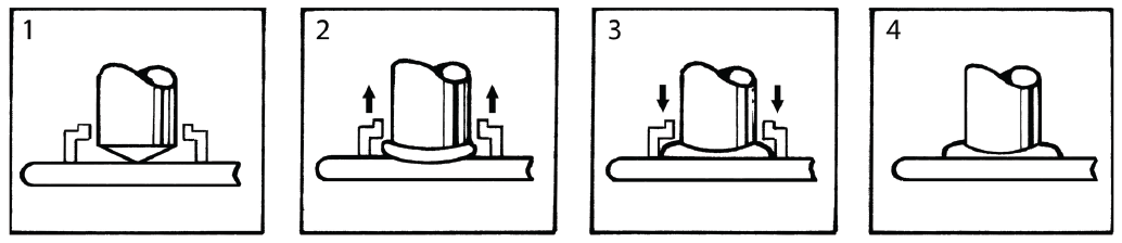
1) The weld gun is positioned over the base material and the main gun spring is partially compressed.
2) The trigger is pressed and the stud lifts off the base material drawing an arc. The arc melts the end of the weld stud and the base material below. The arc shield (ferrule) concentrates the heat below the weld stud and contains the molten metal within the weld zone.
3) The main spring plunges the weld stud down into the molten pool of metal in the base material.
The cycle is completed in less than a second and the resulting weld bond develops the full strength of the fastener in the weld zone.
4) The weld gun is withdrawn from the weld stud leaving the ferrule. The ferrule is then broken
away and discarded.
ARC Stud Locating: Center Punch, Template & Bushing Design
Center Punch Method
By making a center punch mark in the base material the operator can place the fluxed tip of the stud into the punch mark for locating the ARC Stud.
Contact your Complete Stud Welding Sales Representative for proper set-up of the stud welding gun for welding with a center punch.
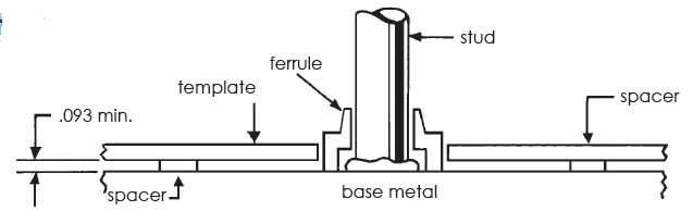
This method of templating is recommended by Complete Stud Welding for use with ferrules. The template is usually a steel plate 3/32” to 3/16” thick. Spacers are required to allow the gases to escape during the welding cycle. The ferrule can be held by a standard ferrule grip or where clearance is prohibitive a tube type set-up can be used. The recommended hole size on the template to locate the ferrules should equal the maximum outside diameter of the ferrule plus 1/32”. Holes may be drilled or bored at required locations. See stud specification sheets for ferrule details. For further assistance contact your Complete Stud Welding representative.
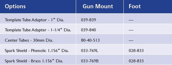
Bushing Method
This method of templating is recommended by Complete Stud Welding for use with all arc stud styles. The design makes it possible to accurately hold angular alignment of the studs as well as stud location. The template should be made of ebonite or masonite of a thickness sufficient to afford good alignment. Template bushings may be used to insure greater accuracy and extend the life of the template. Standard ferrule grips are used with the tube adapter. This permits standardization of templates since it is only necessary to change the ferrule grip to weld studs of different diameters. The hole diameter of the bushing or template should be approximately .010 larger than the maximum outside diameter of the template tube adapter.

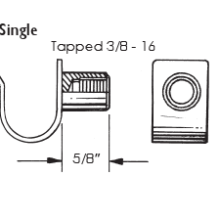
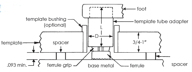
Accommodating the Fillet
When the arc stud is welded, a fillet forms around its base with the dimensions being closely controlled by the design of the ferrule. Since the diameter of the fillet is generally larger than the diameter of the stud, some consideration is required in the design of mating parts. Counterbore and countersink methods are commonly used. Dimensions will vary with studs and ferrules.
Additional Methods of Accommodating the Fillet
Additional methods of accommodating the fillet include
oversized clearance holes, use of a dog-type construction or
use of a gasket material around the fillet.

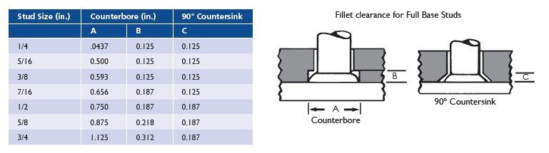
Reduced Base Studs are designed so that the weld fillet does not exceed
the maximum diameter of the fastener. This design is not recommended
if full thread diameter fastener strength is required.
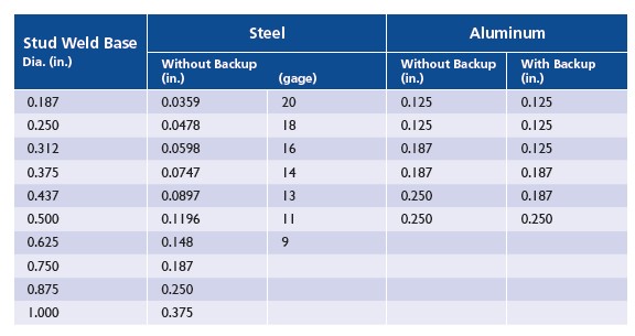
Recommended Minimum Base Thickness
Shielding The Weld
In arc stud welding we either shield the weld utilizing gas or ferrules. Gas shielding is primarily used in industrial applications requiring a stud diameter of 1/2” or less. Please contact your Complete Stud Welding representative for suggestions on the best gas mixes to utilize.
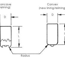
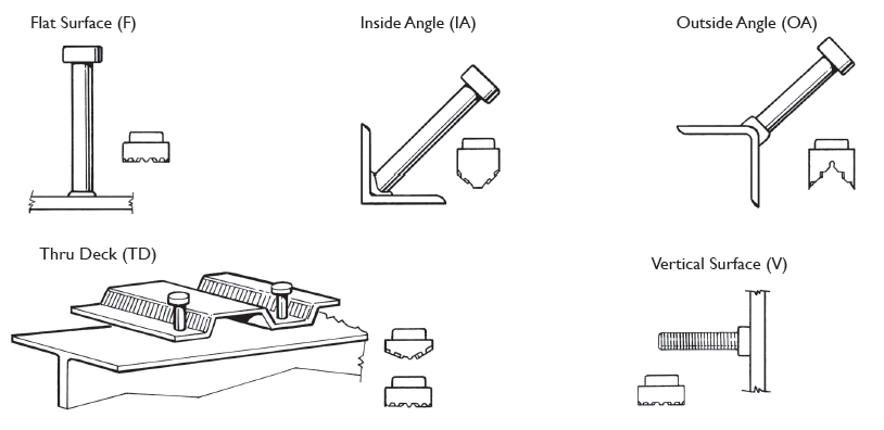
Ferrules are commonly used in industrial and construction applications requiring weld studs from 1/4” to 1” diameter. Specially designed ferrules are needed for some applications. This would include the need to weld to contoured surfaces and welding at angles to the work. Standard ferrules are available for welding to flat, vertical, inside angle, outside angle and thru-deck surfaces. These are shown below:
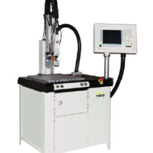
Arc Stud Welding Guidelines & Setting
• Keep weld studs and ferrules clean and dry.
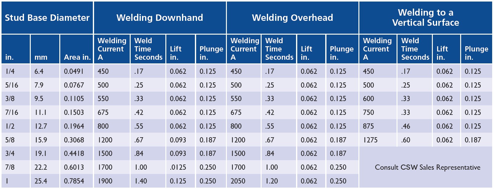
• See chart below for approximate settings for proper equipment setup.
• Make sure the negative polarity is to the weld stud gun and ensure a good, clean ground connection.
• Align accessories so they are centered and adjust legs so that 1/8” to 1/4” of the stud protrudes
beyond the ferrule.
• Make sure work surface is relatively clean so impurities do not affect weld quality.
• Visually inspect all welds for 360° weld flash and for weld flash color (silver, blue & shiny).
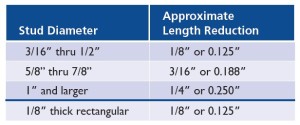
• Check height of welded stud – length reduction equals 1/8”- 3/8”.
• Test the welds at the beginning of each shift or change in stud size. Torque or bend two studs 30
degrees after cooling (AWS Bend Test). See charts for tensile and torque values.
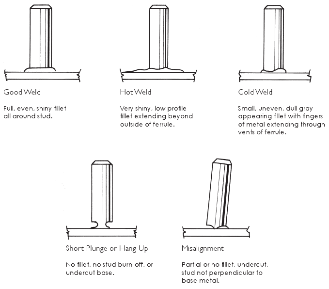
The Complete Stud Welding ARC stud weld can be visually inspected by observing the fillet at the base
of the stud. The illustrations and comments below will assist you in visually judging the quality of the weld.
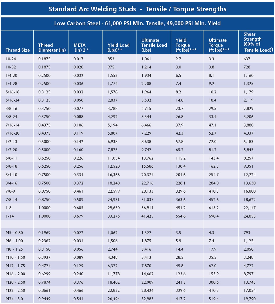
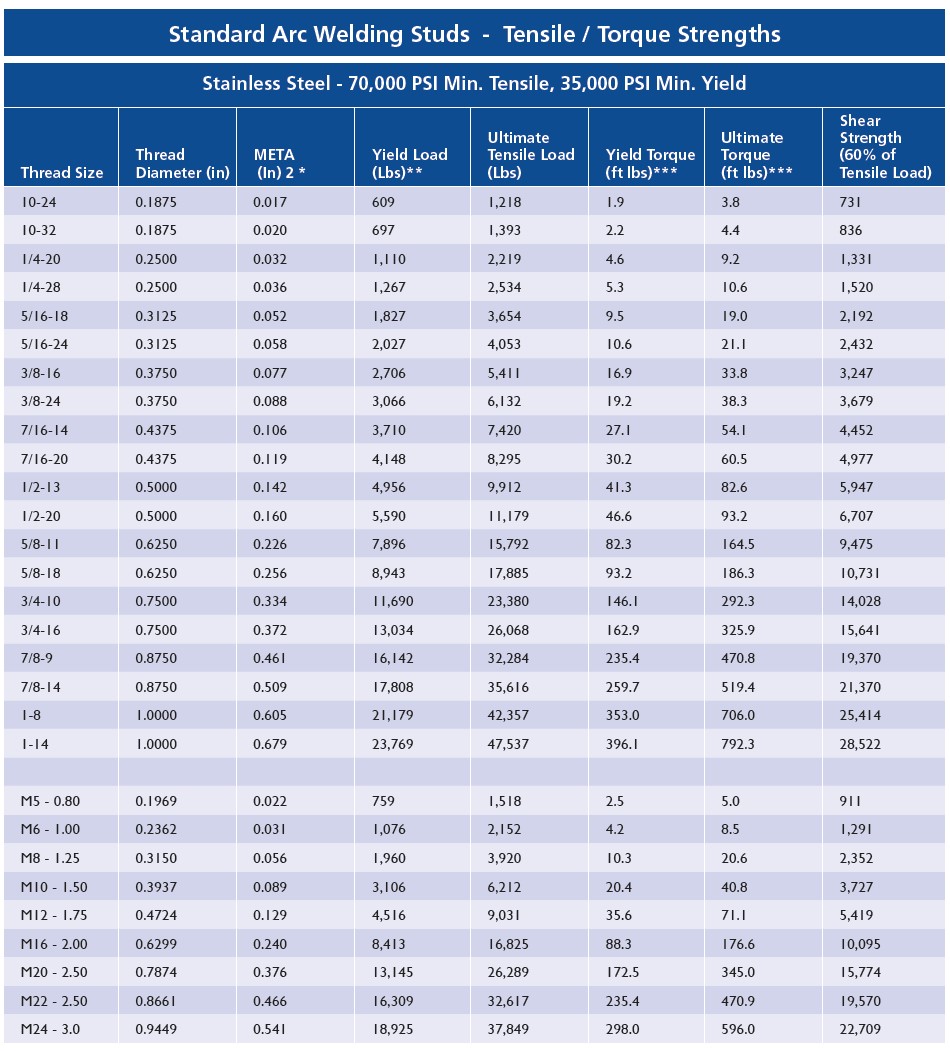
Tensile and Torque Strengths
The following 2 charts are Standard ARC Welding Studs –
Tensile / Torque Strengths.
The data was calculated based on the formulas shown below.
Tensile Load: L = SA
Torque: T= 0.2 x D x L
META*: A= Pi/4 x [D – (0.9743/N)]
A = Mean Effective Thread Area (META)*
D = Nominal Thread Diameter
L = Tensile Load Pounds
N = Threads Per Inch
S = Tensile Stress in PSI
T = Torque in Inch Pounds
*META is used instead of root area in calculating screw strengths because of closer correlation with actual tensile strength. META is based on mean diameter, which is the diameter of an imaginary coaxial cylinder whose surface would pass through the thread profile approximately midway between the minor and pitch diameters.
**Please note, in actual practice a stud should not be used at its yield load. A factor of safety must be applied. It is generally recommended that studs be used at no more than 60% of yield. However the factor of safety may vary up or down, depending on the application. The user will determine the appropriate safety factor.
***Please note, Torque figures based on assumption that excessive deformation of thread has not taken relationship between torque/tension out of its proportional range. All torque figures are shown in foot pounds (ft lbs).
Shear values were calculated at 75% of the Ultimate Tensile Load of the stud.
See next 2 charts on Tensile and Torque Strengths.
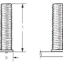
Threaded & No Thread Weld Studs – Technical Details
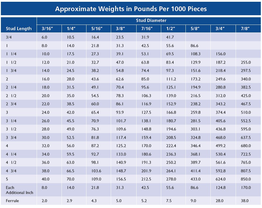
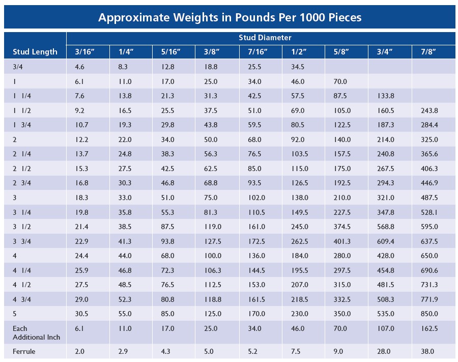
Weight Chart – Threaded Weld Studs
Threaded & No Thread Weld Studs – Technical Details . . . continued
Weight Chart – No Threaded Weld Studs