- sales@completestudweld.com
- 216-904-4008
Capacitor Discharge (CD) Stud Welding Process Description
Process Description:
Capacitor Discharge (CD) Stud Welding involves the same basic principles and metallurgical
aspects as any other arc welding procedure. When the weld gun is activated, a special precision
weld tip initiates a controlled electric arc from the welder capacitor bank which melts the end of
the stud and a portion of the base metal. The stud is held in place as the molten metal solidifies
instantly accomplishing a high-quality fusion weld.
1. The weld gun and stud are positioned against the work.
2. Stored energy is discharged through special weld ”timing” tip and stud starts downward.
3. The stud is forced into the pool of molten metal.
4. Metal solidifies and weld is completed in milliseconds.
Process Advantages:
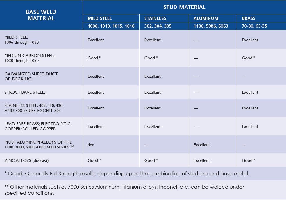
Base & Stud Material Compatibility – CD Stud Welding is compatible with just about any weldable
material, and permits the welding of dissimilar metals. See Chart on the next page for further details.
Reverse-Side Marking – CD Stud Welding is generally used to weld smaller diameter studs to thin
base metals, especially where reverse side marking is not permissible. Since the entire weld cycle is
completed in milliseconds, welds can be made to thin material without pronounced distortion,
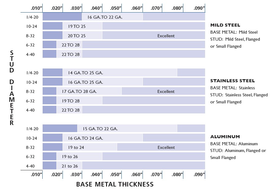
burn-through, or reverse side discoloration. See CD Stud Reverse-Side Marking Guide.
Compatibility of Base Metal & CD Stud Material Combinations
CD Stud Reverse-Side Marking Guide
The charts below will be of help in determining the best combination of stud weld base size and
base metal thickness. The terms on the charts are defined as follows:
Additional factors that can influence the degree of reverse-side marking are tip size, weld voltage, spring pressure and the CD process used (i.e. Contact versus Gap).
CD Weld Stud Locating Options
Template Method:
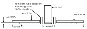
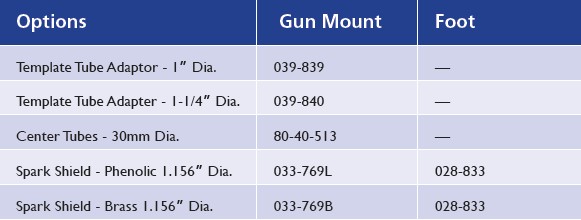
This method of templating is recommended by Complete Stud Welding for use with gun
attachments called “Template Tube Adaptors,” “Centering Tubes” and “Spark Shields.”
These attachments are installed directly onto the gun or used indirectly with a CD foot.
These attachments have diameters of 1”, 1.25”, 1.375” and 30mm. Contact your sales
representative for details.
Scribe Method:
The operator can scribe a mark in the base metal at the location for the stud to be welded.
The scribe mark can either be the center point or can be a circle. With the later, the weld
base diameter of the stud would fit within the circle.
EXAMPLES: X -Locate stud in center of the X.
O -Locate stud in center of the circle.
Center Punch Method: Not Recommended
When the CD Stud Welding Process is being used, the special weld tip on the end of all CD
Type studs should not be used with center punch marks as a method of locating CD Type
studs.
The diameter and length of the special weld tip controls the time duration of the CD Stud
Welding Process and is absolutely critical in obtaining welds that develop full fastener
strength. Accordingly, the introduction of a center punch mark interferes with the timing of
the CD Stud Welding process and will result in weld failures.
CD STUD WELDING GUIDELINES
The following guidelines should be followed for producing and maintaining good CD Stud Welds:
• Ensure the stud welding equipment is capable of welding the stud size intended to be welded.
• Ensure the Stud Welding Equipment is in proper working order and that all cable and ground connections are tight.
• Weld surface cleanliness. The surface should be free from excessive oils, grease and other lubricants and from rust, mill scale, and other oxides. These conditions contribute to high electrical resistance in areas of welding and grounding.
• Weld surface imperfections, such as extreme roughness, which can prevent complete fusion in the weld area and or interfere with the time duration of the process, should be avoided.
• The stud axis must be perpendicular to the work surface to obtain complete fusion.
• Proper weld end design of the stud is necessary. The tip size, weld base diameter and face angle must be correct for the application.
• The operator should follow the equipment manufacturer’s setup parameters (i.e.. Weld voltage, Spring pressure, Plunge and when using GAP or Drawn Arc Method, Lift).
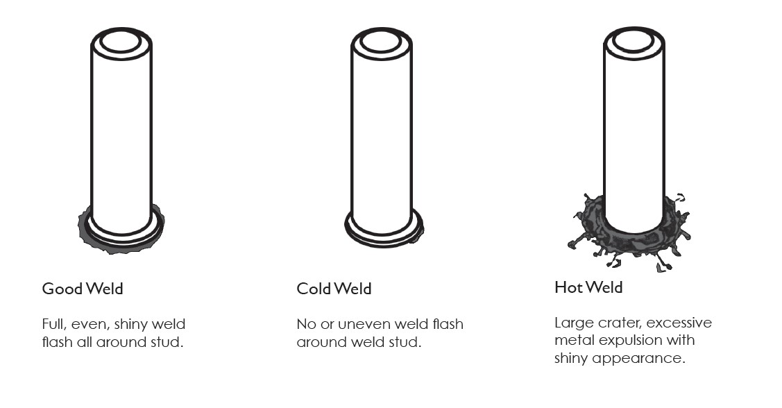
• Visually inspect all welds for 360 degree weld flash. See next page for illustrations of Good, Cold and Hot welds. If a questionable weld is evident after the welds have been visually inspected, the weld should be mechanically tested.
• Mechanically test 2 welded studs at the start of each shift and change in stud size.
• Mechanical Testing of CD stud welds should be done by bend testing or torque testing. The tests are used to establish welding conditions and qualify production studs. The stud and or
weld may be tensile tested and or submitted to other forms of destructive or non-destructive testing as the application requires.
• The bend test should be performed by bending the stud 30 degrees by striking with a hammer or, preferably, bending with a pipe.
• Torque values are given in the subsequent table for various stud materials and stud diameters.
CD STUD WELD INSPECTION – VISUAL
The CD stud weld can be visually inspected by observing the weld flash at the base of the stud.
The illustrations and comments below are intended to assist in visually judging the quality of the weld.
For assistance, contact your Complete Stud Welding Sales Representative.
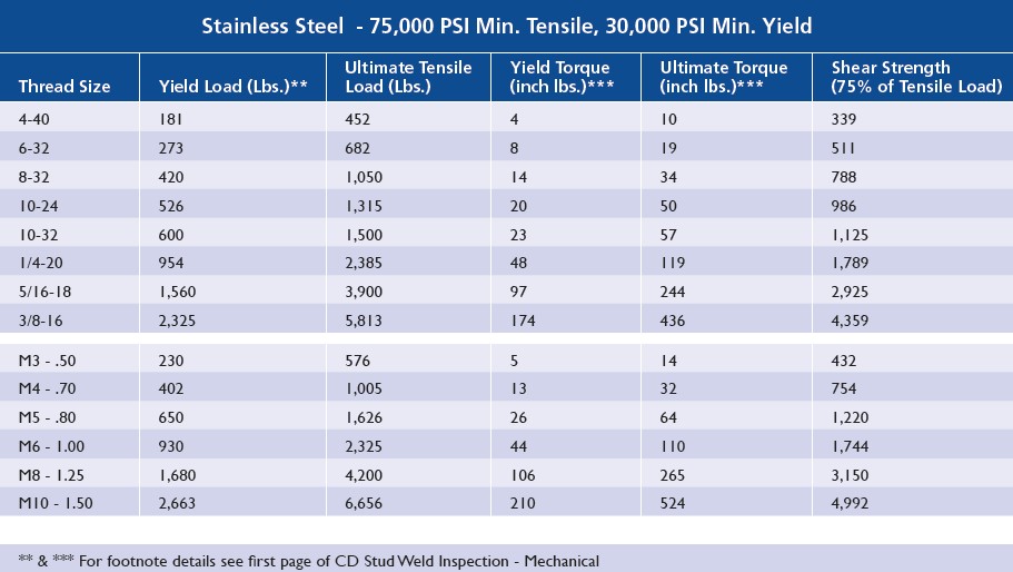
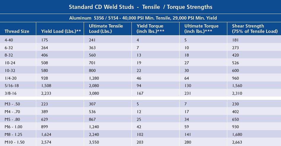
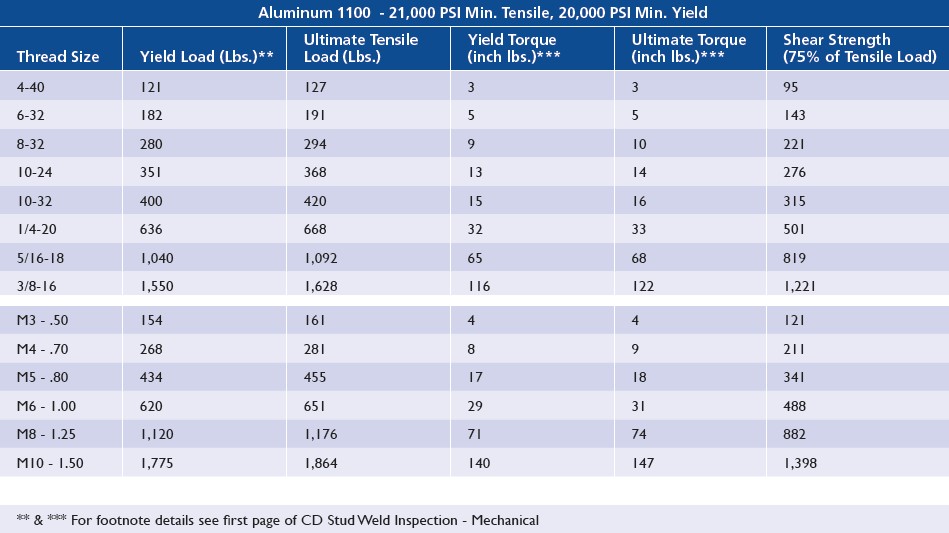
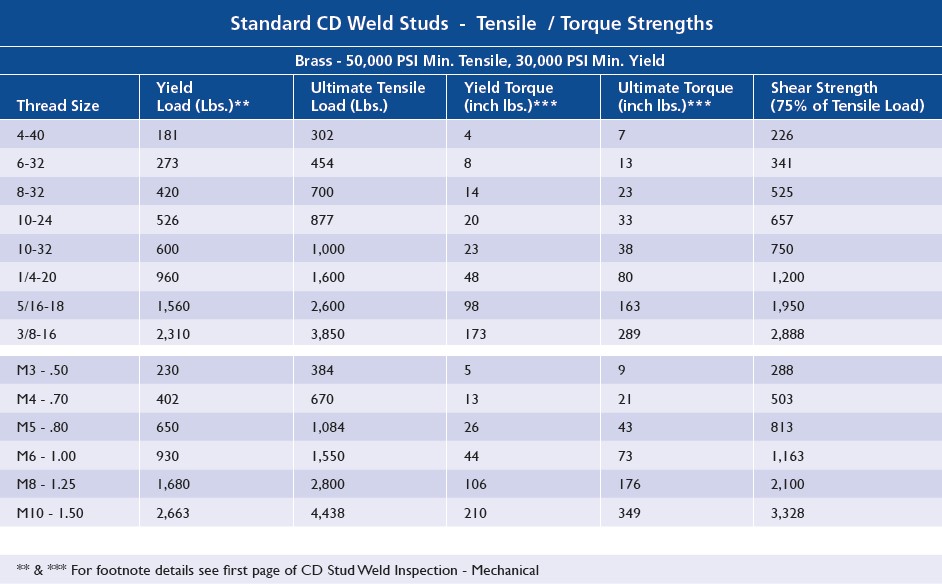
CD STUD WELD INSPECTION – MECHANICAL – tensile / torque strengths
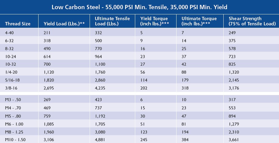
The following 3 pages of charts contain CD weld stud – Tensile / Torque Strengths.
The data was calculated based on the formulas shown below. These formulas and the
notes below are considered integral parts of the Tensile/Torque Strength charts that follow.
Tensile Load: L = SA
Torque: T= 0.2 x D x L
META*: A= Pi/4 x [D – (0.9743/N)]
A = Mean Effective Thread Area (META)*
D = Nominal Thread Diameter
L = Tensile Load Pounds
N = Threads Per Inch
S = Tensile Stress in PSI
T = Torque in Inch Pounds
* META is used instead of root area in calculating screw strengths because of closer correlation with actual tensile strength. META is based on mean diameter, which is diameter of an imaginary coaxial cylinder whose surface would pass through the thread profile approximately midway between the minor and pitch diameters.
** Please note, in actual practice a stud should not be used at its yield load. A factor of safety must be applied. It is generally recommended that studs be used at no more than 60% of yield. However the factor of safety may vary up or down, depending on the application. The user will determine the appropriate safety factor.
*** Please note, Torque figures based on assumption that excessive deformation of thread has not taken relationship between torque/tension out of its proportional range.
Shear values were calculated at 75% of the Ultimate Tensile Load of the stud.
See next 3 charts on Tensile and Torque Strengths
** & *** Applies to subsequent Tensile / Torque Strength Charts.
CD STUD WELD INSPECTION – MECHANICAL – tensile / torque strengths
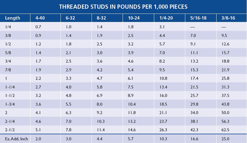
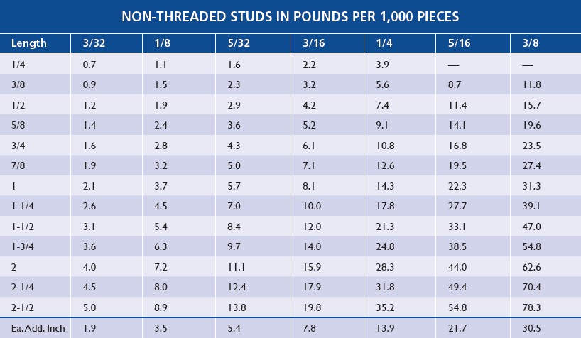
WEIGHT CHARTS – CD FLANGED MILD STEEL STUDS
CD Weld Studs- Standard Stock Sizes
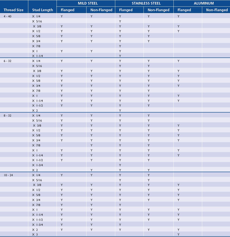
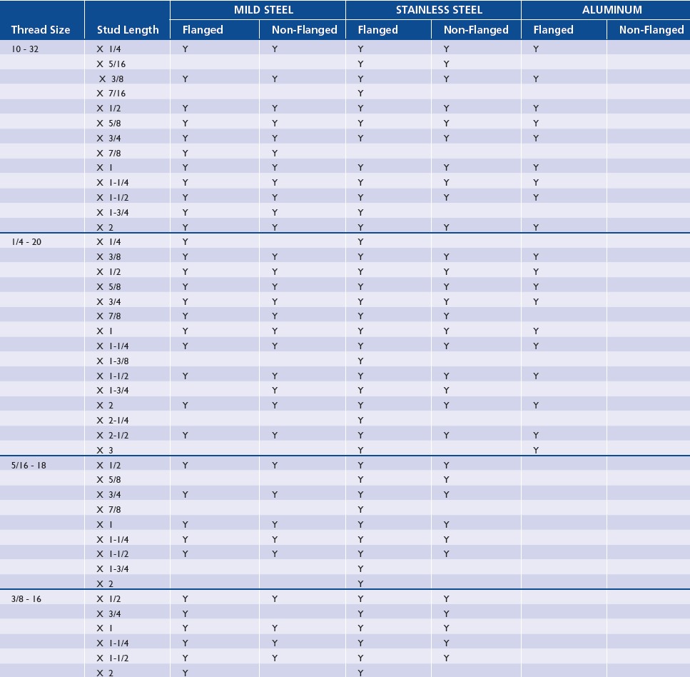
The attached information indicates the THREADED CD Weld Studs that are considered to be “Standard Stock Sizes.” This means that 99% of the time these studs will be in stock.
• The attached information does not cover the vast inventory of CD Weld Studs that are:
• “Threaded CD Weld Studs NOT Considered to be “Standard Stock Sizes” that are in stock.
• Non Threaded CD Weld Studs that are in stock.
• Other Styles of CD Weld Studs that are in stock.
Contact your Complete Stud Welding Sales Representatives for assistance.
CD Weld Studs- Standard Stock Sizes
