- sales@completestudweld.com
- 216-904-4008

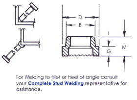
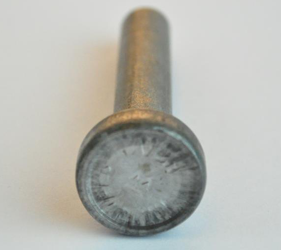
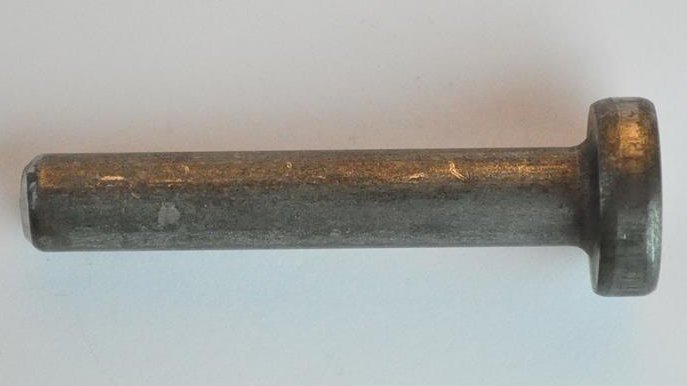
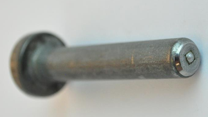
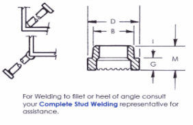
Headed Concrete Anchors are used in all types of concrete connections. They can be welded to a flat surface, inside of an angle or outside of an angle.
Specifications – HCA’s meet AWS Specifications D1.1, D1.5 and or D1.6. International Specifications BS5950, BS5400, DIN/ISO are available.
Material – Low carbon steel, ASTM A108 / A29, Grade C1010 to C1020. In Stainless Steel, grades 302, 304, 310 and 316 are stocked in some sizes.
Ferrules – Customer to specify ferrule type at time
of order.
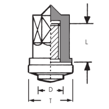
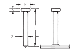
Length – Lengths are listed before welding. For Stud Diameters (D) 1/2” and smaller the length reduction is roughly 1/8” and for (D) 5/8” the reduction is roughly 3/16”. HCA’s can be made in any length above the standard minimum.
Accessories – For a complete list of accessories required with each ferrule type, please see below.
| A | B | C | D | E | F | G | H | I | J | K | |
|---|---|---|---|---|---|---|---|---|---|---|---|
|
1
|
Stud Specifications | Ferrule Specifications | |||||||||
|
2
|
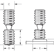
D | H | A | No. | D | B | G | M | |||
|
3
|
1/4 | 0.5 | 0.187 | F025-F | 0.455 | 0.38 | 0.234 | 0.39 | |||
|
4
|
3/8 | 0.75 | 0.281 | F037-F | 0.64 | 0.505 | 0.234 | 0.39 | |||
|
5
|
1/2 | 1 | 0.281 | F050-F | 0.795 | 0.65 | 0.25 | 0.438 | |||
|
6
|
5/8 | 1.25 | 0.312 | F062-F | 1.03 | 0.785 | 0.328 | 0.516 | |||
|
8
|
|||||||||||||||
|---|---|---|---|---|---|---|---|---|---|---|---|---|---|---|---|
|
9
|
Type A | Type B | |||||||||||||
|
10
|
Tensile Strength | 61,000 psi min. | 65,000 psi min. | ||||||||||||
|
11
|
Yield Strength | 49,000 psi min. | 51,000 psi min. | ||||||||||||
|
12
|
Elongation (% in 2 in.) | 17% min. | 20% min. | ||||||||||||
|
13
|
Elongation (% in 5x dia.) | 14% min. | 15% min. | ||||||||||||
|
14
|
Reduction of Area | 50% min. | 50% min. | ||||||||||||
|
15
|
Type A Studs are general purpose studs. | ||||||||||||||
|
16
|
Type B Studs are headed, bent, or of other configuration that are used as an essential component in composite beam design and construction. | ||||||||||||||
| A | B | C | D | E | F | G | |
|---|---|---|---|---|---|---|---|
|
1
|
Stud Diameter | Chuck P/N | Ferrule Type | Ferrule P/N | Foot P/N | Grip P/N |
Ferrule Foot Plate P/N (Dual Leg)
|
|
2
|
1/4” | CN-050 | Flat | F025-F | B-1C | GC-025 | QN-025 |
|
3
|
Low Profile | F025-LP | B-1C | GC-025 | QN-025 | ||
|
4
|
Heavy Duty | F025-HD | B-1C | GC-037 | QN-037 | ||
|
5
|
Inside Angle | F025-IA | B-1C | GD-025 | N/A | ||
|
6
|
Outside Angle | F025-OA | B-1C | GC-025 | QN-025 | ||
|
7
|
3/8” | CH-037 | Flat | F037-F | B-1C | GC-037 | QN-037 |
|
8
|
Low Profile | F037-LP | B-1C | GC-037 | QN-037 | ||
|
9
|
Heavy Duty | F037-HD | B-1C | GC-050 | QN-050 | ||
|
10
|
Inside Angle | F037-IA | B-1C | GD-037 | N/A | ||
|
11
|
Outside Angle | F037-OA | B-1C | GC-037 | QN-037 | ||
|
11
|
Weld Thru Deck | F050-TD | B-0021 | B-0060-2 | N/A | ||
|
13
|
1/2” | CH-050 | Flat | F050-F | B-1C | GC-050 | QN-050 |
|
14
|
Low Profile | F050-LP | B-1C | GC-050 | QN-050 | ||
|
15
|
Vertical | F050-V | B-1C | GC-050 | QN-050 | ||
|
16
|
Heavy Duty | F050-HD | B-2C | GC-062 | QN-062 | ||
|
17
|
Inside Angle | F050-IA25 | B-1C | GD-050 | N/A | ||
|
18
|
Inside Angle | F050-IA37 | B-1C | GD-050 | N/A | ||
|
19
|
Outside Angle | F050-OA | B-1C | GC-050 | QN-050 | ||
|
20
|
Weld Thru Deck | F050-TD | B-0021 | B-0060-2 | N/A | ||
|
21
|
5/8” | CH-075 | Flat | F062-F | B-2C | GC-062 | QN-062 |
|
22
|
Low Profile | F062-LP | B-2C | GC-062 | QN-062 | ||
|
23
|
Vertical | F062-V | B-2C | GC-062 | QN-062 | ||
|
24
|
Heavy Duty | F062-HD | B-2C | GC-075 | QN-075 | ||
|
25
|
Inside Angle | F062-IA25 | B-2C | GD-062 | N/A | ||
|
26
|
Inside Angle | F062-IA37 | B-2C | GD-062 | N/A | ||
|
27
|
Outside Angle | F062-OA | B-2C | GN-062 | QN-062 | ||
|
28
|
Weld Thru Deck | F062-TD | B-0021 | B-0060-2 | N/A |
Headed Concrete Anchor – Standard Sizes
| A | B | C | D | E | F | G | H | I | |
|---|---|---|---|---|---|---|---|---|---|
|
1
|
Specifications | Packaging Detail | Weights – in pounds | ||||||
|
2
|
Diameter | Length | CSW Part Number (mild steel) |
Pieces Per Box |
Boxes Per Pallet |
Pieces Per Pallet |
Box Weight |
Pallet Weight |
1,000 Pcs. Weight |
|
3
|
D | L | |||||||
|
4
|
1/4 | 1 – 1/8 | HCAM0250112 | 2,000 | 27 | 54,000 | 48 | 1,296 | 24 |
|
5
|
2 – 11/16 | HCAM0250268 | 1,000 | 27 | 27,000 | 45 | 1,215 | 45 | |
|
9
|
3 – 1/8 | HCAM0250312 | 1,000 | 27 | 27,000 | 51 | 1,377 | 51 | |
|
6
|
4 – 1/8 | HCAM0250412 | 600 | 27 | 16,200 | 39 | 1,053 | 65 | |
|
7
|
3/8 | 1 – 1/8 | HCAM0370112 | 1,000 | 27 | 27,000 | 70 | 1,890 | 70 |
|
8
|
1 – 5/8 | HCAM0370162 | 1,000 | 27 | 27,000 | 79 | 2,133 | 79 | |
|
9
|
2 – 1/8 | HCAM0370212 | 700 | 27 | 18,900 | 67 | 1,809 | 96 | |
|
10
|
2 – 5/8 | HCAM0370262 | 600 | 27 | 16,200 | 66 | 1,782 | 110 | |
|
11
|
3 – 1/8 | HCAM0370312 | 500 | 27 | 13,500 | 62 | 1,674 | 124 | |
|
12
|
4 – 1/8 | HCAM0370412 | 350 | 27 | 9,450 | 55 | 1,485 | 157 | |
|
13
|
5 – 1/8 | HCAM0370512 | 300 | 27 | 8,100 | 56 | 1,512 | 187 | |
|
14
|
6 – 1/8 | HCAM0370612 | 200 | 27 | 5,400 | 44 | 1,188 | 220 | |
|
15
|
8 – 1/8 | HCAM0370812 | 250 | 27 | 6,750 | 69 | 1,863 | 276 | |
|
16
|
1/2 | 1 – 1/8 | HCAM0500112 | 600 | 27 | 16,200 | 68 | 1,836 | 113 |
|
17
|
1 – 1/2 | HCAM0500150 | 500 | 27 | 13,500 | 68 | 1,836 | 136 | |
|
18
|
1 – 5/8 | HCAM0500162 | 450 | 27 | 12,150 | 64 | 1,728 | 142 | |
|
19
|
2 – 1/8 | HCAM0500212 | 400 | 27 | 10,800 | 67 | 1,809 | 168 | |
|
20
|
2 – 5/8 | HCAM0500262 | 350 | 27 | 9,450 | 71 | 1,917 | 203 | |
|
21
|
3 – 1/8 | HCAM0500312 | 300 | 27 | 8,100 | 68 | 1,836 | 227 | |
|
22
|
4 – 1/8 | HCAM0500412 | 200 | 27 | 5,400 | 56 | 1,512 | 280 | |
|
23
|
5 – 5/16 | HCAM0500531 | 150 | 27 | 4,050 | 52 | 1,404 | 347 | |
|
24
|
6 – 1/8 | HCAM0500612 | 125 | 27 | 3,375 | 49 | 1,323 | 392 | |
|
25
|
8 – 1/8 | HCAM0500812 | 100 | 27 | 2,700 | 50 | 1,350 | 500 | |
|
26
|
10 – 1/8 | HCAM0501012 | 75 | 27 | 2,025 | 51 | 1,377 | 680 | |
|
27
|
12 – 1/8 | HCAM0501212 | 1500 | 1 | 1500 | 1095 | 1120 | 1095 | |
|
28
|
5/8 | 1 – 7/16 | HCAM0620143 | 400 | 27 | 10,800 | 85 | 2,295 | 213 |
|
29
|
1 – 11/16 | HCAM0620168 | 325 | 27 | 8,775 | 77 | 2,079 | 237 | |
|
30
|
1 – 15/16 | HCAM0620193 | 300 | 27 | 8,100 | 78 | 2,106 | 260 | |
|
31
|
2 – 1/8 | HCAM0620212 | 250 | 27 | 6,750 | 68 | 1,836 | 272 | |
|
32
|
2 – 3/16 | HCAM0620218 | 250 | 27 | 6,750 | 71 | 1,917 | 284 | |
|
33
|
2 – 11/16 | HCAM0620268 | 250 | 27 | 6,750 | 81 | 2,187 | 324 | |
|
34
|
3 – 3/16 | HCAM0620318 | 200 | 27 | 5,400 | 75 | 2,025 | 375 | |
|
35
|
3 – 11/16 | HCAM0620368 | 150 | 27 | 4,050 | 75 | 1,674 | 413 | |
|
36
|
4 – 3/16 | HCAM0620418 | 150 | 27 | 4,050 | 62 | 1,863 | 460 | |
|
37
|
4 – 11/16 | HCAM0620468 | 125 | 27 | 3,375 | 69 | 1,701 | 504 | |
|
38
|
5 – 3/16 | HCAM0620518 | 100 | 27 | 2,700 | 55 | 1,485 | 550 | |
|
39
|
6 – 9/16 | HCAM0620656 | 90 | 27 | 2,430 | 55 | 1,485 | 611 | |
|
40
|
8 – 3/16 | HCAM0620818 | 80 | 27 | 2,160 | 52 | 1,404 | 650 | |
|
41
|
9 – 3/16 | HCAM0620918 | 150 | 9 | 1,350 | 117 | 1,053 | 780 | |
|
42
|
10 – 3/16 | HCAM0621018 | 100 | 9 | 900 | 98 | 882 | 980 | |
|
43
|
For non standard sizes contact your Complete Stud Welding Representative. | ||||||||
Product Images